RCC Electronics Technical Application Note
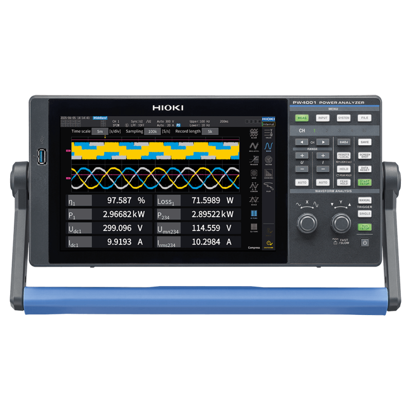
Why Choose the Hioki PW4001?
A fair, source-backed comparison with the Yokogawa WT1800R for motor, inverter, VFD, fan and field power measurements.
The short answer
Choose the Hioki PW4001 when four channels cover the application and accuracy, current-sensor integration, fast updates and portability matter. Choose the Yokogawa WT1800R when the test truly needs five or six power channels, built-in 5 A or 50 A direct current inputs, simultaneous dual-source harmonics, or an established Yokogawa laboratory workflow.
What both analyzers have in common
Both are precision power analyzers designed for power conversion, motor and energy-efficiency work. Both support single- and three-phase wiring, voltage, current and active-power measurement, power factor, phase angle, efficiency and loss calculations, integration, external current sensors, waveform viewing, harmonic analysis, optional motor analysis, LAN, USB and remote control.
Six reasons the PW4001 often wins the application
- Lower analyzer error at DC and power frequency. At DC and 50/60 Hz, PW4001 specifies ±(0.03% of reading + 0.01% of range), compared with WT1800R at ±(0.05% of reading + 0.05% of range). The lower range term is valuable when the signal is below full scale.
- A lighter instrument that can leave the laboratory. PW4001 is approximately 4.6 kg and 135 mm deep. A six-element WT1800R is approximately 14 kg and 459 mm deep. PW4001 also supports optional 10.5 V to 28 V DC power and operates from −20°C to 50°C.
- Integrated current-sensor workflow. With compatible Hioki sensors, PW4001 automatically identifies the sensor and compensates its phase characteristics, reducing setup mistakes and improving confidence in low-power-factor measurements.
- Four channels cover many complete drive tests. PW4001 can measure a DC bus plus a three-phase output using 3V3A, or two three-phase sections using the two-wattmeter method.
- Faster routine data updates. PW4001 offers 1 ms, 10 ms, 50 ms and 200 ms update intervals. WT1800R normal update intervals start at 50 ms, although it provides a separate high-speed capture function.
- Interfaces for modern control development. PW4001 configurations support CAN/CAN FD input and output, BNC synchronization, LAN, USB and D/A output.
Hioki PW4001 vs Yokogawa WT1800R
| Decision factor |
Hioki PW4001 |
Yokogawa WT1800R |
| Power channels |
4 fixed, isolated channels |
1 to 6; WT1801R through WT1806R |
| 50/60 Hz power accuracy |
±(0.03% reading + 0.01% range) |
±(0.05% reading + 0.05% range) |
| Sampling |
2.5 MS/s, 16 bit |
Approximately 2 MS/s, 16 bit |
| Normal data update |
1, 10, 50 or 200 ms |
50 ms to 20 s or Auto; separate high-speed capture |
| Current architecture |
External Hioki sensors; PW9100A current boxes for 50 A measurement |
Built-in 5 A or 50 A elements; optional external-sensor inputs |
| Sensor support |
Automatic recognition and phase correction with compatible Hioki sensors |
External sensor ratio/range configuration; optional six-channel sensor power supply |
| Harmonics |
Wideband to 500th; optional IEC harmonics and flicker |
Optional G5 to 500th; G6 simultaneous dual-source harmonics |
| Field power |
Optional 10.5 V to 28 V DC operation |
100 V to 240 V AC |
| Operating temperature |
−20°C to 50°C |
5°C to 40°C |
| Approximate mass |
4.6 kg |
14 kg for a six-element unit; 16 kg with sensor power |
Note: Accuracy values are six-month specifications under the manufacturers’ reference conditions. Reading and range terms must be calculated separately at the actual operating point.
Where the WT1800R is the better decision
- Five or six power channels: WT1805R and WT1806R keep larger multi-circuit or dual-3V3A tests inside one chassis.
- Direct 5 A or 50 A current: Built-in shunt inputs can eliminate an external sensor and its associated amplitude and phase errors.
- Existing Yokogawa infrastructure: WTViewerEfree, IS8000, ScopeCorder correlation and established WT automation code may outweigh a main-unit specification advantage.
Large fan and VFD measurement examples
- DC bus + three-phase VFD output: 1 + 3 channels; PW4001 fits.
- Three-phase input + three-phase output using two-wattmeter methods: 2 + 2 channels; PW4001 fits.
- Three-phase input + three-phase output, both using 3V3A: 3 + 3 channels; WT1806R is the cleaner single-instrument configuration.
Accuracy belongs to the complete system
Analyzer headline accuracy is only one part of the measurement. At the selected voltage and current ranges, include the analyzer reading term and range term. When an external sensor is used, also include its ratio/amplitude, range, phase, frequency and temperature terms. At low power factor, even a small sensor phase error can dominate active-power error.
RCCE therefore recommends selecting the analyzer and current sensor together.
RCCE recommendation
For a portable four-channel system measuring a large fan, VFD, motor, vehicle or power converter, start with the Hioki PW4001. Move to the WT1800R when the application truly needs five or six power channels, direct 5 A/50 A inputs, dual-source harmonics or an established Yokogawa workflow.
View Hioki PW4001 Ask RCCE for a configuration
Manufacturer sources
- Hioki PW4001 official product page
- Hioki PW4001 basic specifications
- Hioki PW4001 general specifications
- Hioki PW4001 official features
- Yokogawa WT1800R official product page
- Yokogawa WT1800R official brochure
Scope: Specifications were checked against manufacturers’ published materials. Options, firmware and availability can change. Confirm exact suffix codes and sensor configuration before ordering. This is an engineering selection guide, not a calibration certificate.